Friday, December 3, 2010

First train up the main line


Well, today was a big day on the Northern Central. I built the frame of the first control panel on the main line and then mounted it to the side of the substructure at the town of Herndon. This panel will essentially be for the tower operator who will control the moves through Herdon, including the crossovers. Picture one shows it clamped to the frame of the table as I drilled the holes and placed screws from the rear. The torpedo level ensured we were level and square. The I mounted a terminal strip as seen in the second shot and began to hook up the block power wires to the strip. As I hooked up each block, I ran a diesel powered test train up and down to be sure it was wired correctly. You can see this in the third shot. After it was all done, I put together an I1sa powered freight train and ran the first freight over the main from one end of the completed track to the other. It really looked good snaking out of the storage yard in the distance as seen in the last shot.
I was seated at eye level to the train as it rumbled up the main right by me. I felt like I was along a the main line - oh, the wonders of O scale. This makes all the effort worth it.
Tomorrow we host about 24 men coming down from Baltimore and DC so I hope it rus as well as it did today!


Wednesday, December 1, 2010

Bridges over the Susquahanna

I just wanted to show you where the main line will cross the Susquahanna on twin bridges and then bear right around the wall, going past the engine terminal. You can see the turntable pit off in the distance in the second shot.
Construction will have to stop for a while as I go back to wiring and a control panel or two so I can test what is already down.


Just about done


Well, after a long struggle, the framing is in place and the legs are added to the structure. You can see it took quite a few legs to hold up such a large expanse. In the second shot, you can see the framing for the turntable. The third shot shows where the main will enter from the right, crossing the double tracks below and then curve off towards the pole. The engine storage will then fill the expanse to the left.
I have not cut and secured the top as I have a large group coming this Saturday and do not have time to complete that. I have to move into a major clean up to make it all presentable.


Adding the cross members to the yard


Well, after the help had gone, I had a lot of cross members to put up. They were quite long so I needed some way to support them while I attached them to the perimeter. You can see in the third photo that I got a roller support for my table saw and used it with a long box as the middle support. This came after a lot of pieces fell to the floor as I tried different approaches.
First I put the short leg onto the perimeter as seen in the first two shots. While this torqued the side rail, I was able to take that out once I had he support in place.
After all the long members were done, I added blocking because I needed to tie everything together due to the expanses. Later I added legs in the center as well. It came out pretty strong as I was able to use the cross members as parallel bars with no flexing.
You can see I had to use a lot of clamps in the process as I had to put a long straight member above the member I was joining together to be sure that it was straight as well. You can see that set up in the third photo. The legs went on last, once I had all the cross members and the bridging in place..


Outling the area


As we are looking at a very large area, I thought I could put the exterior framing together and then raise it up to make putting the interior in easier. Well, it turned out to not be easy at all but I found that out after I was underway. The kids were here for Thanksgiving so I used my three son-in-laws to help me get it up on temporary legs . My wife only allowed me to have the guys in the basement for an hour so that was all I could get done.
You can see the framing is in place and the special corner work has been attached. All the other cut pieces are on the floor. We did mark the rails where those cross sections were to go but I had a lot of splices to make as I am working with 8 foot pieces. You do get a better sense of the size once it was in the air.

Making curved corners


Well, now for some fancy footwork! I did not want right angle corners around the engine terminal area as I think we might see a lot of traffic there as everyone comes over to see those I1's and M1's that will be stored in the area. We will also have some Alco PA's burbling away in the diesel area.
So, just like building a wooden model airplane, we have to make some formers. The first shot shows two cut out of 3/4 inch plywood. They will form the top and bottom of the corner. I also had to cut an inset for the bendable plywood so it would be flush with the side rails.
In the second shot, you can see the two plates in place, along with the special cuts I had to make in the side rails to tie them in. I made tongues to mate up with the bendable plywood and match the depth of the inset cuts in the 3/4 inch plywoood. I also backed the side rail up with 1 inch by 1 inch reinforcing to strengthen the joint.
The third shot shows how they looked after they were in place and then covered with the bendable plywood. In the last shot, you can clearly see how the 3/4 plywood ties into the side rail and the bendable plywood then makes the corners. I am pleased how they came out.


Starting to make the engine facility framing


Okay, we have the diagram on the floor and now we begin to cut the framing to match the drawing. I also decided to make curved corners using a technique that Pat Mitchell showed me on my previous layout. In the first picture we are looking back to the east and you can see how the engine area comes off the main line which is curving to the left. This is why we have the diagonal edge to the benchwork. We will also have an open pit that an operator will be able to access to reach the yard throat should we have a problem in the future. Thanks to John Roberts and Ed Rappe for that suggestion. My problem is that this is a very large expanse and given it will be high at 51 inches off the floor, an individual's reach will be limited. As the runs are about 16 feet, I had to change the direction of the framing in the area under the diesel storage. You can see this in the second shot as you look above the turntable. The diesel house will be running left to right over that framing. We have to stop here as I need to do some testing of the lower track to be sure it is safe to cover it up with the yard.
The next step will be to make the special framing for the curved corners.


Starting to layout the yard


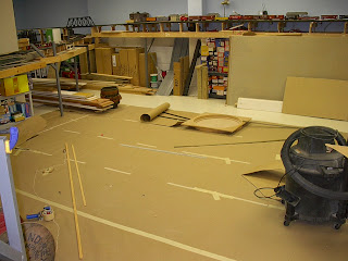
So, now that we can see clearly, we start to layout the engine terminal area as the main comes into the yard. First we cover the floor with our brown paper so we can transfer the information from the computer design onto it. This gives us our actual dimensions. You can see the straight edges and the bendable wood stringers that I use to get easement curves. The tracks will come around the corner from the beige wall in the distance and then curve to the left. the steam engine terminal will be the first thing we pass on the right. You can see the approximate location of the turntable on the floor. The roundhouse will be to its left. The dimensions of the 6 stall roundhouse are drawn on that roll of brown paper you see. I am surprised by how large it is. The benchwork will actually come all the way to the shop vacuum as the diesel house will be right above that point.
I have also erected a beam over Herndon the get the angle that I will need to allow the yard to cover the 8 storage tracks below. You can see that clearly in the first photo. I was a bit disappointed that the angle was so shallow that I lost a whole corner of Herndon so I have to rethink the layout of that town. I believe I will have a road bridge cross the tracks at that same angle so the tracks disappear into a tunnel under the bridge. More on that later.

Adding light to the subject


Well, it has been some time since I have posted - mea culpa, mea culpa, mea maxima culpa! I have been very busy with several issues but I have not neglected the layout.
I was able to buy a large number of commercial lighting fixtures at a very low price ($5 per) so I went around and put over 35 up in the place of the twin bulb shop fixtures I originally installed. This took a little time as I had to rewire some of the ceiling to rebalance the bulb count by light circuit as I was adding so many bulbs ( going from 2 to 3 and 4 bulb fixtures). I actually melted a light switch due to a slight overload. Fortunately, I was right there and no damage other than to the switch occurred. You can see in the photos that the light fixtures have full reflectors which made a terrific difference. I feel like I am in an operating theater now. It makes it so much better to work on the layout. So, all construction stopped as I was in the ceiling above. I located the higher intensity lights over the aisles and left the twin bulb units over the areas where the scenic dividers will go later. In the first picture, the light in the right foreground is a twin. The lights in the right distance are the new ones. They look like spot lights in comparison.