Friday, January 21, 2011

Extending the yard substructure - Part 3


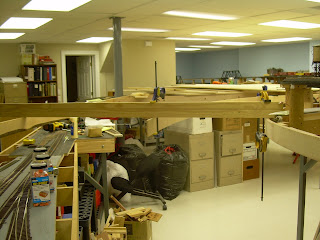
In order to give you the best understanding of our challenge, I took these photos looking back on the curved section. The first shot looks down the new aisle that we are creating. You can see the pine framing member on the temporary support at the lower left. This has to be tapered into the curved plywood in the center of the photo. You can just make out the gold clamp holding it up.
The second shot shows how we will be above the lower yard - it will become the hidden yard. You can see the framing on both sides of the yard.
The third photo shows this area from the other side, where you can see the bend in the 16 foot 1X4 that forms the outer member of the structure. I will be using the steel rod to hold this up as it crosses over the tracks in the foreground as it is very oblique and thus a long span.
The saga continues!

Additional development of yard benchwork - Part 2


As we progress, you can see that I have added internal bracing for the yard in the area of the curved face that forms the aisle. I set the bent plywood face runner, measured a cross member and installed it wih screws and glue. It was still suspended from the wood across the framing. You can see the progress in the first two photos. I then glued another laminate of the bendable plywood to the one in place for strength and used a bunch of clamps to hold it until it set. After that I clamped some temporary legs in place. You can see this in the third photo. You can also more clearly see the start of the aisle as it necks down at the peak of the curve.
In the fourth and fifth photo, I have moved further around the corner and am laying in a piece of pine to see how to frame the next length of substructure. I have clamped a Y shaped riser to the end of the benchwork of the lower yard so I can rest a 1X4 that I then suspended from that cross member. I am trying to determine where I have to kerf it so I can bend it to meet the plywood piece coming in from the right.
My next major activity will be to make some L type cross members from two pieces of pine to reduce the depth of the framing member while keeping it strong as I have to have some overhead room over those lower yard tracks.
This is starting to get really complicated as I have to figure out how to support this yard structure over the lower tracks. I think we may have to use some steel rod as well as wood.


Extending the yard substructure


Well, this is a confusing series of photos that show how I am moving to extend the benchwork to provide for the yard. I have to make a curved bend in the benchwork to bear to the right as we look down the last photo. You can see the left perimeter of the benchwork as it bends the most radically. The right perimeter is the length of pine that bends slowly after it passes the grey column.
In the picture with the horizontal clamps in the center, you can see that I am using a bendable plywood to define the interior of the frame. It will also set the aisle width to the left of the clamps. I have suspended the future benchwork from a board that crosses from the existing framework of the branch line to the right perimeter of the future benchwork.
The two top pictures show the suspension of the future benchwork and you can also see how we are going over the top of the hidden yard that was completed earlier.
I am having a problem as I have to maintain a minimum width of the yard at 39 inches so I can fit in all the tracks and still have room for the interior aisle. It appears that I will have a pinch point at the peak of the curve with the aisle going down to 24 inches from its previous minimum of 36 inches.


Going underground


Well, I have not posted for a while as I have not had too much surface progress. I have been underground wiring up the turnouts in Herndon. The photo shows a Circuitron switch motor with a wiring clip attached to it. The other photo shows the clips laying out on top of the turnouts in the hidden yard. They have to be installed next. I have prewired 8 lengths of code 19 wire to the clip. It provides motor power to the switch motor, and wiring for two sets of switches internal to the motor. They power the turnout and any lights we might want. So, in the under the track work, I have hooked up the turnout motor to the power supply, and the switch to a wire going to the frog. The other three wires are hanging there for a future connection.