Tuesday, February 16, 2010

Process for hanging brackets - Part Two


We now have the hole drilled in the bracket and it placed back into the marks on the beam that Rich made previously. With this registration, we should be close to where we want to be. Rich is showing how we then drop the plumb bob down to check it against where we want it on the roadbed. We move the bracket in small adjustments to get it exactly where we want it. Then Rich screws it to the joist. After it is set, we again go back to the plumb bob and mark exactly where it meets the roadbed so I can drill it to receive the TEE nut that will be the base connection to the rod that will hold the roadbed to the ceiling.
Each bracket takes about 15 minutes to place. I am now down to the last two of approximately 50 that I have placed. Next posting will be to show the layout of the turnouts in the throat of the loop, before it is raised.


The process for hanging the brackets


Here in two posts is how we locate and hang the overhead brackets.
First, we roughly locate the bracket by placing it with clamps and then checking with the plumb bob that it is approximately where we want it. Rich then marks the beams to indicate where the bracket is located so we can place it back there. He also marks on the bracket where he sees the rod will intersect it. I take the bracket to the shop and drill a 1/4 inch hole at that spot with a drill press, to be sure that the hole will be vertical.

Rich then places a brass fitting that I made on the lathe that has the plumb bob string through the middle into the hole that I drilled on the press. This ensures that, while the hole is 1/4 inch in diameter for the rods that will be inserted, the string is centered.
In the next post, we will wrap up the process.


Saturday, February 13, 2010

Placing hangers for the overhead


We are now at the stage of placing the overhead hangers and then drilling the roadbed at a point directly below the hanger so a steel rod can be threaded into the TEE nut to hold it up. I will try to get a series of action shots to show the process in my next post.
In these shots you can see that I have painted the base of the roadbed a grey color after the addition of all the homasote. The second, third and fourth shots all show the completed roadbed and its location. The first shot shows what the hangers look like. They are pieces of 2 by 4, screwed to the underside of the TGI's with a hole drilled in them to accept the threaded rod. Directly below them, shown in the fifth photo is a hole drilled on the edge of the roadbed , one inch in from the edge. These holes are spaced 20 inches apart to try to give enough support so the plywood will not flex.
The process involves spotting the hanger using a plumb bob, directly over the mark on the roadbed. Then I drill the hanger, with a drill press to ensure it is a vertical hole, and place it on the TGI. Again with the plumb bob, we recheck the location over the mark, and make any minor adjustments needed. Then we drill the roadbed and place the TEE nut in the underside of the roadbed. Each placement takes about 15 minutes of measuring, drilling and screwing in. We have about 52 to do. More to follow when we do more tomorrow.


Thursday, February 11, 2010

Laying the roadbed on the overhead loop


We now are laying the homasote roadbed on the overhead loop. The six tracks are more obvious now. I cut the strips of homasote to be the same width as the track. It is also kerfed so I can bend it to make the curves. We followed those pencil lines laid out by the trammel to position them.
We added biscuits in the ends of the plywood sections to align the pieces vertically. We then placed doubler plates of 1/2 inch thick plywood at each joint. This will allow us to rest the new piece we put up to the ceiling on the previously hung one so we can just add two pieces of steel rod at the opposite end to hold it while we get the other rods in. These pieces are gaining weight as we add the homasote and can be unweildy.
The last picture is a bit busy and distant but you can see all the homasote is in except for the last sections where I have to lay out the turnouts that spread the tracks into the six loops. I used an air nailer to nail the homasote down and that is the air hose laying in front. You can also see a rough outline of how the turnouts will go in. I am waiting for some additional turnouts to come so I can complete this section. In the meantime I have painted the whole assembly battleship grey to clean it up.
As usual, when you get into construction, tools and other things come out so the clean basement is not so clean any more.


Layout of the overhead loop


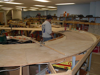
Rich Feller came over and we placed the previously cut (done in 1995) plywood on top of the lower storage yard roadbed. This plywood for the overhead loop was something I designed many years ago and then I had a fellow with a computer driven router system cut out of 3/4 inch furniture grade birch plywood. I have moved the material three times to now when I can finally install it.
Rich is standing where we laid out 6 tracks to ensure we had the clearances that I had designed in - 4 inch separation in the track radii
(note the trusty pencil and calculator). In the third shot you see the trammel in the foreground, which we used to draw the guide lines for the tracks so we have a template to lay the roadbed. In the last shot you see Rich standing by the throat of the loop which looks like a big balloon. It will be a single track coming up the hill that then opens up to a loop of 6 tracks for storage of the branch line trains that are being exchanged with the Lehigh Valley RR in Mount Carmel. This was the end of the Shamokin Branch.
The roadbed is positioned directly below where we will raise it to within 12 inches of the ceiling. The tiles are coming out so we can put the brackets in the ceiling to hold the steel threaded rods that will hold the plywood up. Look out Gotthells, here I come!


Begin to prepare the room for the overhead loop


Here is a shot of the last lobe of the room that has not had any construction in it yet. In the first picture, you can see the piles of stuff that had accummulated here as the work went on in other parts of the room. I also had shelves full of train boxes that are now under the frame of the layout that is already built.
I disposed of a great deal of boxes, and stuff that I thought I could use but never did. The trash man got a real workout. In the last two pictures you can see the results of the work. The shelves of magazines on the left wall in picture three await a location but everything else has been placed somewhere or thrown out. The last picture looks back to where the branch comes around the corner in the center of the picture where the blue paint ends. The lower storage area is in the left rear.