Wednesday, October 18, 2017

Working on Crowl

 I am making all these posts at one time to catch up but I had  taken pictures of the work in progress over time. We have been pressing to get things done since last summer before an open house in November . One night in September, the group was working on finishing the ground cover near Crowl as the photo mural was in place and we wanted to blend everything together. Here Paul is putting dirt on a road behind the Paxinos area.
 The rest of the guys are getting the green down. You can see the mural on the wall and how it blends with the 3D scenery in front of it.
More of the group and the scene.

Tuesday, October 17, 2017

Putting in A Stone Retaining Wall

 As I looked at the design of the hill below the abutments of the bridge, it became apparent that it was going to be pretty steep. My cohorts argued for a taller retaining wall than I wanted to make and they convinced me it was more appropriate for the hill that we would create. You can see here that we have a big height differential to deal with.
 So, I started by gluing blocks to the road bed base. These blocks would hold the bendable plywood backer for the retaining wall. You can see the clamps holding the distant blocks in place. We placed them on a curve determined by holding the plywood a set distance from the edge of the ballast line of the track.
 I cut a piece of plywood about 5 inches high and about 5 feet long.
 Here we have the plywood in place and glued tot he backer blocks. I had to cut down the left end of the plywood as I would be bringing the wall lower as it ended.
 I checked to see that the backer was low enough to be hidden but high enough to provide the support I needed.
 I had to cut each panel of the wall in such a way as the base matched the grade while the stone rows and top stayed horizontal. Essentially, I had to cut across two rows of stone within the length of each panel to match the grade. You can see the step effect here.
 Here I have cut down the last panel. I had to cut the ends of the panel in a step fashion to bring the wall down to termination.
 You can see the termination here. I have to coat the top of the stones with body putty to cover the expanded foam that wall is made from.
Here is a backside view of he whole assembly glued together. I had to let the glue dry for two days to get a good grip on the foam and the wood. Next, on to the cardboard base for the hillside.

A Culvert for Crowl

 I have taken an HO Chooch culvert and made it into a culvert for Crowl. I liked the stone construction as it is typical of the PRR in this area. I first glued the castings to  a Masonite base that I painted with a concrete color.
 I then added some wood guides and took a half a roll core from a toilet paper roll and painted it black in the inside.
 I glued the core to the base and the casting and painted the interior floor black also. It is long enough that one cannot see out the other side.
 I had made an opening in the plaster work as we put the plaster finish coat on - I used the casting as a guide for the outline that we left.
Here is the finished product inserted into the scenery. Now I have to plaster it in and bring the scenery products up to it.

New Trackage to Bridge

 Well, as we approach the bridge we have to go through a junction for Shamokin and the Glen Burne Colliery. I had two custom made turnouts done that match the curvature of the approach track for the bridge. So here we see the installation process underway.
 I have laid the ties, sanded them and then placed the turnouts. They are held in place by printed circuit board ties so it has been a relatively painless process. The only problem is that the pc ties are only half thickness so I will have to put some wood beneath them to fill the open space.
 Here is the view looking towards the bridge. The turnout to the left leads to what will become the yard at Shamokin.
 The track curves nicely onto the approach to the bridge.
Here we look towards the other side which will take a lot of effort!

Thursday, August 24, 2017

The Big Bridge!!

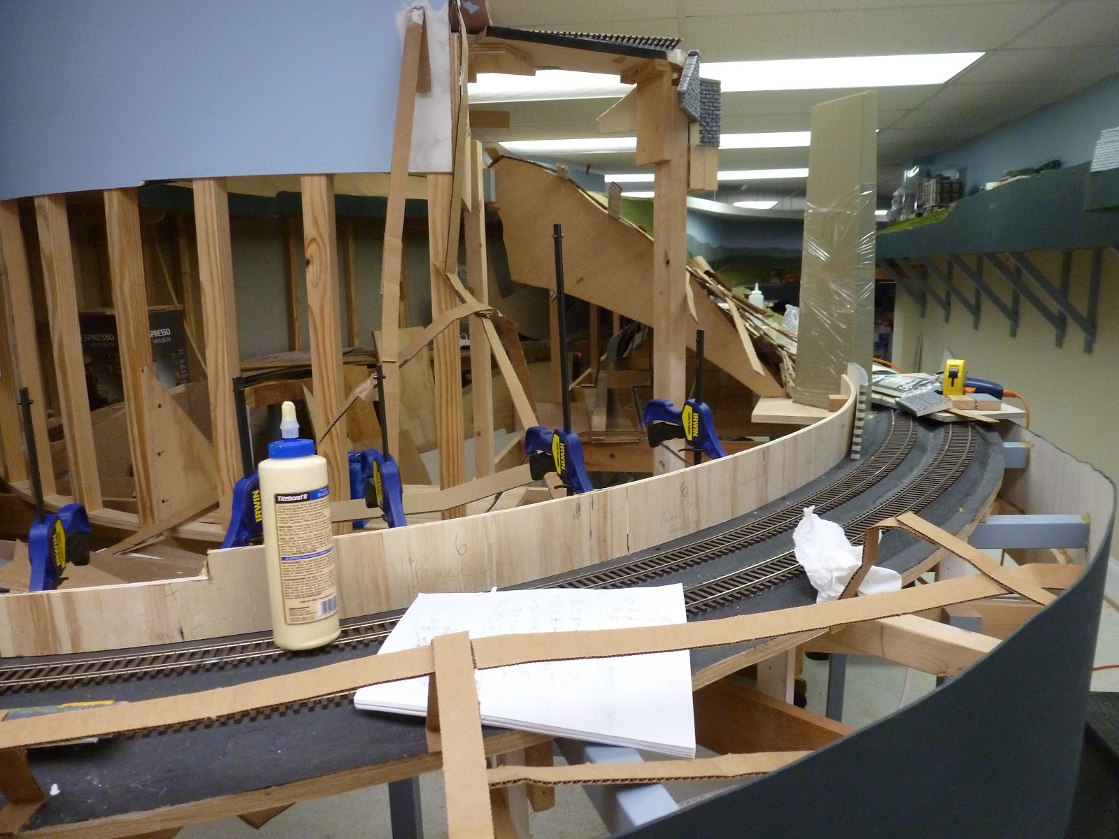
 Well, this is an exciting series of photos to post as I have been trying to get this bridge in for about 2 years. You have seen the photos and story about the building of the deck girder bridge, the painting of the through truss, and Alan's work on fabricating the main pier based on a design from Bert Sacco, an old friend up in New England. So, we are now tackling the main project and i feel like I am working for the American Bridge Company, a division of USS Steel. So, as I had waited so long, I just balanced that main pier in place after cutting out the temporary structure that had been in use for about 5 years. I was worried because if that fell over, I was in big trouble!
 It certainly look good in the pictures and I was happy that I was building it but still worried about the execution. The big problem was where the main pier would end up and if it would interfere with the main line below.
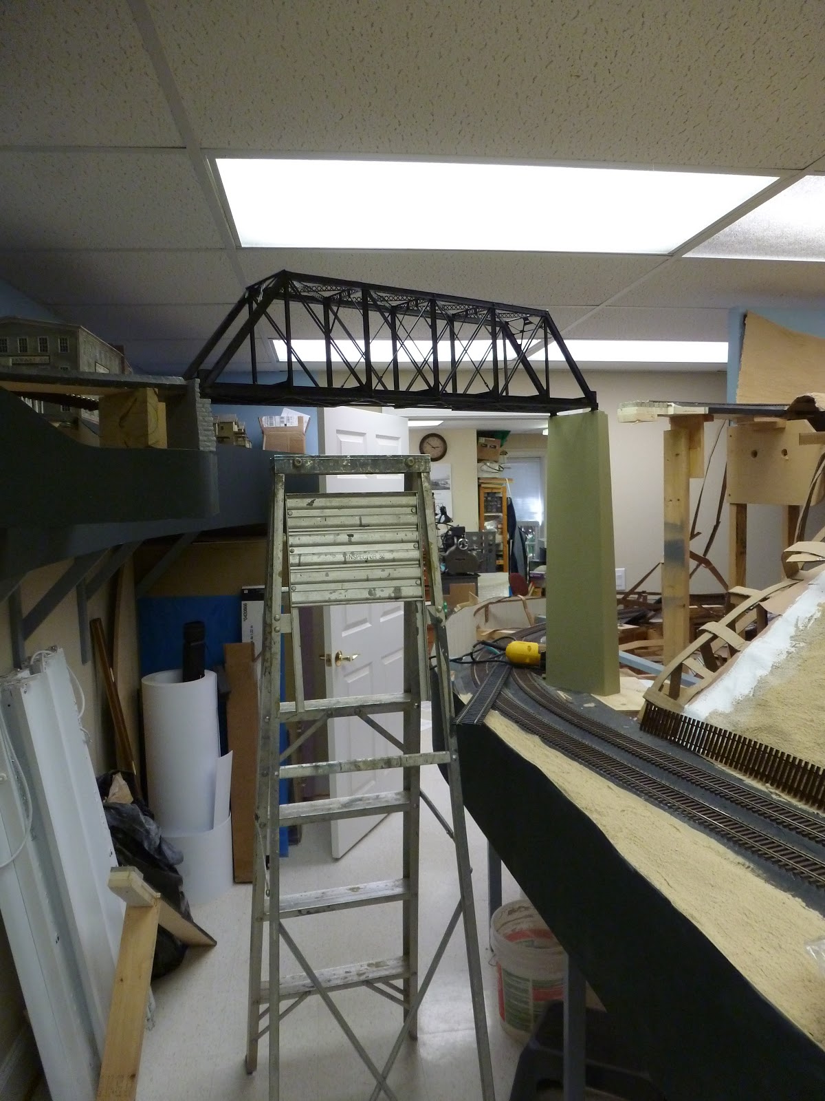
 Checking the height clearance - made for a self portrait and made me happy that there is plenty of head room for a 6 footer.
 It does look imposing over the aisle. Now we have to get after the specifics.
 I used a long board as a template for the height required - a suggestion from the crew. Stop messing with the bridge and tempting fate! So, I have braced the pier in place and taken a board and placed it on the pier. I drew the dimension of the through truss bridge on it to be sure the pier would be in the right place. It appeared to be high.
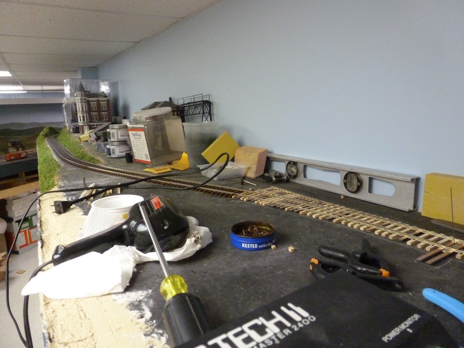
 To check that dimension, I glued a cleat on the end of the road bed so I could measure down to where the deck should be.
 Next, I had to level the pier as it was on a sloped grade. So, I cut the subroadbed and placed offset braces underneath to make the base level. It raised the pier about a quarter of an inch.
 Now that the cleat is in place, it was pretty obvious how much off I was.
 I had to move the pier to get it located exactly and it is right at the edge of the adjusted grade. With all of that done, I determined I had to cut 3/4 of an inch off the base to make that piece of wood hit the cleat. To do that, I had to brace the pier to make the base perpendicular to the saw. Took some adjustment but it worked. When put in place, everything came out fine.
 Now I have to screw in the pier from below while holding it vertical. So, I placed some blocking around it, drilled pilot holes in the subroad bed and the pier and got below the table. Needless to say, I was nervous but it worked and nothing fell down!
 Here is the work site just after drilling and screwing. I used that big gold NMRA gauge to be sure we had clearance on the pier and the inner track. It just clears due to the super elevation tilting the track towards the pier.
 The pier was perfect and plumb so I was elated. I placed the bridge on it and it fit perfect. Looks good too!
 Now I have to put in the deck girder. First I had to trim the roadbed back to make it fit. Then I had to measure where the pier would go.
 So, you can see the base of the pier has been attached to the riser. I sanded the pier base to get an exact fit.
 Here I am testing the level of the pier with some bridge ties and a straight piece of wood to see where the rail will hit the rail on the hill side. Looks good.
 Looking back into the through truss looks good as well. A nice smooth flow.
 The bracing looks good from below. Glad I made it open.
The bridge looks imposing which is the effect I wanted! Now for all the finish work - scenery, track, etc! Nothing is easy.

Finishing ground forms at Crowl

 Well, I finished the plaster work at Crowl and painted the basic ground color. Then came the slow and careful removal of the plastic covering that protected the photo. Here we see the east end of the area with the start of the photo backdrop. The white line is the base for the local road that will disappear into the scenery.
 Looking back east towards the farm house in the photo, you see  an overview of the area. The small building will be the Crowl Store. A culvert also has to be completed.
 As we step back, it really looks good.
 This is the west end of the area that will be blended into the town of Snydertown. Some large buildings will cover the corner.
 A couple more views
 Looking down the whole area. Shows the sweep of the track as well.
 The last bare shot shows the road base coming in to the scene.
 A couple of days later and the ground cover crew is working to make things look better. Paul is our road builder so he is working on putting a smooth covering on that. The ground cover crew has already been through the area. The photo is being pulled into the scene. I like it.
We have a new member, Tim, and he is putting on the green and brown ground cover. He is working with our master gardener, Mike.
 Mike is working back towards Paul and you can see how nice things look with some green added.
 A action shot of the whole crew from last Monday night.
 The finished section. The road stands out for now. We have to go back next with some rough turf and greenery to give more dimension to the area. The black surface is where the Shamrock water tank and a section house will go.
It really has blended the photo into the scene!