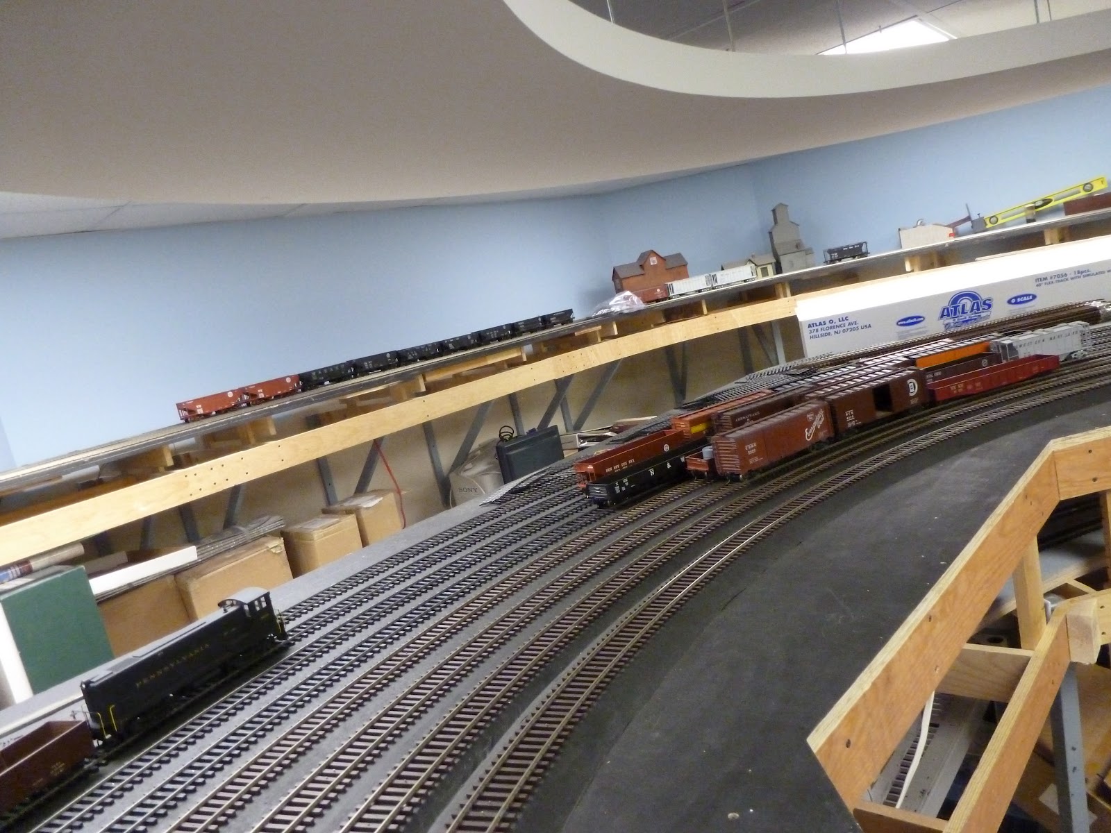
Well, we have finally completed the yard throat. The double slip was a real bear as I mentioned previously. It took a lot of time to get everything to work together. I have not put in the machines yet but have gotten the bulk of the work done, completing the cutting of the ties today.
It has a nice flow to it with the top turnout leading into the yard ladder. I am going to go downstairs to start that after I finish writing this. You can see that I am moving the tools into place.
One last look at the the throat. I have not placed the rail leading to the last frog as I will use the rail going into the next turnout for that. I am going to put a caboose track next to the ladder and that will come off the left track just past where I stopped.
This is where the yard ladder will go. It will consist of 4 number 7 turnouts that then terminate in a 3 way switch that I have to build. It will be located where all those templates are taped to the yard surface at the top left of the picture. I hope to get the ladder done in a week.
Friday, April 13, 2012
Wednesday, March 21, 2012
Building the East End - Part 2
Well, as we come off the curve of the eastbound main, I built the entrance to the yard tracks and the branch line. This first turnout went comparatively well, being finished in about an hour and a half. I had previously laid all the ties in the throat as you can see. I figured the next step would be easy as I had an Old Pullman pre-made double slip switch to cover both crossing the branch and accessing the arrival track.
Well, I was completely mistaken in that belief as the switch was a mess. It did not work and was not in any kind of gauge. So, I had to disassemble it on the bench and then relay it on a shim stock base to hold the frogs in place. Out came the torch as I held my breath and unsoldered all the frogs. I then reassembled every thing and held it all in place with spikes while I used the torch to solder it all together. Then I took it to the layout and it seemed to fit the diagram that I had made. The next problem was the way he had designed the points - they were just to flex by moving the rails - there was no joint or pivot. When I spiked it all down, I realized that the rail was too stiff and I had to make pivots. So, out came the smallest diameter cutting wheel I had to cut through the point rails without cutting the adjacent running rails and then insert rail joiners to provide the pivots. I am now at the 90% point as I have to adjust the frogs that I used to replace the ones he sent. I used cast #8 frogs from Trackside Specialties that really looked a lot better. I have invested about 7 days in this one switch as I have had to stop many times along the way. I am hoping to move right along on the next two turnouts and then lay out the actual ladder. Based on a planning session we had on Monday night, I will have to build a three way turnout at the end of the ladder. It looks like it will be a combination of a #10 and a #7. Am I looking forward to that or what! This is needed to get into the separate steam and the diesel engine servicing facilities. More later!
Sunday, March 4, 2012
Adding the yard tracks
Well, now that we completed the ladder turnouts on the west end of the yard, we have pushed on to install most of the yard tracks themselves. This is a view from the center aisle showing the four yard tracks and the Arrival and Departure tracks along with the two main tracks. I had two open houses recently. One was for a local Model railroad club and the other was for some prototype enthusiasts. I also had a weekend with my grandson. So, I put out some extra cars so we could run some trains. I had a 43 car train running around behind some Sharks. They looked great. Here you see that we put some cars in the yard with a switch

engine, a Baldwin unit. This is a closer view of it. This is a test train to run back and forth as I test the track. All is well so far.
Here is a view from the other side as I stand in the main aisle. We are looking towards the east end of the yard. I plan to lay track down to where I have to build more switches.
A higher shot, further down the yard, looking east. The last track to the right is not actually laid down as I have to build the run around track there and I was checking clearances.
Here is the end of the line. I have to build the ladder switches and the crossings to get into the yard on the east end.
Here we are at the east end and you can see the switch templates are down so I can check my alignments and make sure it will all flow well.
A higher view that shows the location of a double slip that will be the second switch in from the east bound main track. I have checked the framing under the top and I seem to be able to fit it all in. I have not checked that on the ladder turnouts yet. but am keeping my fingers crossed.
A closer view showing where the ladder will go - next to where you see that aluminum rod to the left that ends under the soldering iron.
Here is a distance shot looking back into the yard with the branch high on the wall in the rear. The flow of the yard is nice but I am concerned about the coupling on a curve issue. There are plenty of curves in this yard. It looks like Clifton Forge on the C&O.
engine, a Baldwin unit. This is a closer view of it. This is a test train to run back and forth as I test the track. All is well so far.
Here is a view from the other side as I stand in the main aisle. We are looking towards the east end of the yard. I plan to lay track down to where I have to build more switches.
A higher shot, further down the yard, looking east. The last track to the right is not actually laid down as I have to build the run around track there and I was checking clearances.
Here is the end of the line. I have to build the ladder switches and the crossings to get into the yard on the east end.
Here we are at the east end and you can see the switch templates are down so I can check my alignments and make sure it will all flow well.
A higher view that shows the location of a double slip that will be the second switch in from the east bound main track. I have checked the framing under the top and I seem to be able to fit it all in. I have not checked that on the ladder turnouts yet. but am keeping my fingers crossed.
A closer view showing where the ladder will go - next to where you see that aluminum rod to the left that ends under the soldering iron.
Here is a distance shot looking back into the yard with the branch high on the wall in the rear. The flow of the yard is nice but I am concerned about the coupling on a curve issue. There are plenty of curves in this yard. It looks like Clifton Forge on the C&O.
Friday, February 17, 2012
Completing the west end yard ladder - Part 5
As you can see, we have completed the ladder turnouts and laid the west end of the yard tracks. All the turnouts are number 6's due to the need to blend into the curve that forms the end of the yard. The radii are pretty big so coupling should not be a problem. I have yet to lay the caboose track which will come down in the foreground and then eventually tie back into the ladder.
This is a view of the last two switches in teh ladder and a shot of the ladder tracks. The brown track at the toop right is the start of the thoroughfare track.
Here we are going about the curve. One track is still to be laid in the foreground and the piles of track are for that one.
Continuing around the curve. You can see the two main lines, the arrival and departure tracks and the four yard tracks. You might be able to make out the center line for the last track just under the brown ties and rail and the right side of the picture.
This is the end of the line. I have to do more subroadbed work beyond here.
This is the view looking east and you can see the work that has to be done.
This is the view of the east end of the yard and that is the next phase of construction. The homasote is now down so I have to prepare it for painting and then layout the turnout locations. The papers on the track to the right are the turnout diagrams.
This is a view of the last two switches in teh ladder and a shot of the ladder tracks. The brown track at the toop right is the start of the thoroughfare track.
Here we are going about the curve. One track is still to be laid in the foreground and the piles of track are for that one.
Continuing around the curve. You can see the two main lines, the arrival and departure tracks and the four yard tracks. You might be able to make out the center line for the last track just under the brown ties and rail and the right side of the picture.
This is the end of the line. I have to do more subroadbed work beyond here.
This is the view looking east and you can see the work that has to be done.
This is the view of the east end of the yard and that is the next phase of construction. The homasote is now down so I have to prepare it for painting and then layout the turnout locations. The papers on the track to the right are the turnout diagrams.
Sunday, February 12, 2012
Building the West End of the yard - Part 4
Well, we are entering the yard area from teh Number 8 crossing show in the previous post. Looking down the drill track (yard lead) we first built a number 6 turnout to lead into the caboose and RIP track to the right. The straight track leads to the Arrival and Departure tracks.
Now you can see that the caboose track is loosely laid on the right - not in its final alignment. It is just sitting near that file. The next turnout built is a number 7 that leads down to the yard ladder on its right. It is a pretty sharp curve at a 63 inch radius. We are transitioning to a lighter rail as we go into the yard. We go from Code 148 to code 125. The Arrival and Departure track lead to the left stays at the same weight of rail as the main - primarily because the supplier of my lighter track has disappeared and I cannot get any more.
We are looking down at the diverging yard lead on the right and the Arrival/Departure lead to the left. That is a number 8 switch that I have built that separates the two A/D tracks. All the turnouts had to be curved to fit them into the space alongside the curving mail line.
Looking back, you can now see the Arrival and Departure tracks where the two freight cars are sitting. I have been test the turnouts with them. You can also see the curvature of the turnouts going back along the lead. I have now laid the ties for the yard ladder turnouts as well.
Looking the other way, the tracks have been laid for the A/D tracks around the curve at the middle of the yard. I have also assembled some flex track using old Atlas ties and some 6 foot long pieces of code 125 rail. It is really nice stuff to work with - too bad it is no longer available right now.
Looking further around the curve. This area is soon to fill up with track as we complete the ladder tracks.
Looking down the long straight to the east end of the yard. You can see that I had to stop laying track as I have to prepare the subroadbed for the new section. You can also see the trammel lines that we drew on the yard base to show the center lines for the tracks. Those track bundles piled there are the last of my Code 125 with brown ties.
This is the old Atlas track with 6 foot length rail. We prepared 10 sections. I have enough rail for another 12 sections and then I have to go back to 3 foot long rail. Those 130 feet of rail will only do three yard tracks so I will have to use the3 foot sections for the other 2 yard tracks. I figure the yard will hold about 225 cars. I also have 6 hidden tracks overhead with a capacity of about 200 cars, and 8 hidden tracks off the main that would hold 2 passenger trains and another 200 cars. So, I think the layout can absorb about 550 cars without paralysis.
This is the yard ladder that we have to work on next. The first pieces of rail are down and now we have to build the four number 6 turnouts that will form the yard proper. I think that J1's will be able to back down the ladder to use the thoroughfare track to get to the engine house as it will be straight. I am a little worried about that curve at the top..
Now you can see that the caboose track is loosely laid on the right - not in its final alignment. It is just sitting near that file. The next turnout built is a number 7 that leads down to the yard ladder on its right. It is a pretty sharp curve at a 63 inch radius. We are transitioning to a lighter rail as we go into the yard. We go from Code 148 to code 125. The Arrival and Departure track lead to the left stays at the same weight of rail as the main - primarily because the supplier of my lighter track has disappeared and I cannot get any more.
We are looking down at the diverging yard lead on the right and the Arrival/Departure lead to the left. That is a number 8 switch that I have built that separates the two A/D tracks. All the turnouts had to be curved to fit them into the space alongside the curving mail line.
Looking back, you can now see the Arrival and Departure tracks where the two freight cars are sitting. I have been test the turnouts with them. You can also see the curvature of the turnouts going back along the lead. I have now laid the ties for the yard ladder turnouts as well.
Looking the other way, the tracks have been laid for the A/D tracks around the curve at the middle of the yard. I have also assembled some flex track using old Atlas ties and some 6 foot long pieces of code 125 rail. It is really nice stuff to work with - too bad it is no longer available right now.
Looking further around the curve. This area is soon to fill up with track as we complete the ladder tracks.
Looking down the long straight to the east end of the yard. You can see that I had to stop laying track as I have to prepare the subroadbed for the new section. You can also see the trammel lines that we drew on the yard base to show the center lines for the tracks. Those track bundles piled there are the last of my Code 125 with brown ties.
This is the old Atlas track with 6 foot length rail. We prepared 10 sections. I have enough rail for another 12 sections and then I have to go back to 3 foot long rail. Those 130 feet of rail will only do three yard tracks so I will have to use the3 foot sections for the other 2 yard tracks. I figure the yard will hold about 225 cars. I also have 6 hidden tracks overhead with a capacity of about 200 cars, and 8 hidden tracks off the main that would hold 2 passenger trains and another 200 cars. So, I think the layout can absorb about 550 cars without paralysis.
This is the yard ladder that we have to work on next. The first pieces of rail are down and now we have to build the four number 6 turnouts that will form the yard proper. I think that J1's will be able to back down the ladder to use the thoroughfare track to get to the engine house as it will be straight. I am a little worried about that curve at the top..
Saturday, January 28, 2012
Building the West End of the yard - Part 3
Well, we have cut the main line and built a Number 10 crossing. We then added a number 8 crossing to get into the Arrival and Departure tracks, the yard lead and then into the yard. This view shows the number 10 crossing and the yard lead on the right. We have a temporary bumper at the end of the lead to avoid having cars plunge to the floor below.
This is a close up of one of the number 8's. It shows that I am spiking every tie but not going so far as to use tie plates. I do plan to come back later and add rail braces along the point area. I have not yet made the throw bars as I push on building turnouts.
This is looking back through the number 10's.
Here is another view looking back with the number 8's in the foreground and the number 10's in the rear. The ties are light colored as I sand them down to be sure they are level after the glue dries. I use a template to lay out the turnout so I know when to place the frog for the desired number. I use Right of Way products for the frog and point castings.
This is the number 6 turnout that leads to the caboose track. The line continues through the turnout and then into a number 7 that will provide the lead to the yard ladder. The line continues beyond that into a number 8 that opens up into the Arrival and Departure tracks. You can see that the number 6 has to have its ties trimmed to match the curvature of the rails. I do the trimming after I lay the turnout although I am looking at using a Canter tie jig to pre-trim the ties.
This is an overview of the throat that has to be built. The paper template for the number 8 entrance to the Arrival and Departure tracks is in place. You can see that all the turnouts are slightly curved - another complication.
These are the templates for the number 6's that lead into the yard tracks. I am checking as I go for interference with the joists as I place the points. The switch motors will mount below and I can't have them in the same place as the joists. It appears I have a problem with the first turnout so I will probably stretch that one slightly to place the points to the side of the joist.
This is a close up of one of the number 8's. It shows that I am spiking every tie but not going so far as to use tie plates. I do plan to come back later and add rail braces along the point area. I have not yet made the throw bars as I push on building turnouts.
This is looking back through the number 10's.
Here is another view looking back with the number 8's in the foreground and the number 10's in the rear. The ties are light colored as I sand them down to be sure they are level after the glue dries. I use a template to lay out the turnout so I know when to place the frog for the desired number. I use Right of Way products for the frog and point castings.
This is the number 6 turnout that leads to the caboose track. The line continues through the turnout and then into a number 7 that will provide the lead to the yard ladder. The line continues beyond that into a number 8 that opens up into the Arrival and Departure tracks. You can see that the number 6 has to have its ties trimmed to match the curvature of the rails. I do the trimming after I lay the turnout although I am looking at using a Canter tie jig to pre-trim the ties.
This is an overview of the throat that has to be built. The paper template for the number 8 entrance to the Arrival and Departure tracks is in place. You can see that all the turnouts are slightly curved - another complication.
These are the templates for the number 6's that lead into the yard tracks. I am checking as I go for interference with the joists as I place the points. The switch motors will mount below and I can't have them in the same place as the joists. It appears I have a problem with the first turnout so I will probably stretch that one slightly to place the points to the side of the joist.
Thursday, January 19, 2012
Building Turnouts
Okay, so now we have to cross over from the east bound main to the west bound main as we want to be able to enter the yard. So, the first step is to cut the track that was already installed and lay out the ties for a Number 10 crossover. Both turnouts will be on slight curves with some super elevation at each end. This view shows the ties down and a track diagram on the far end.
Once the glue has set up, I sanded the tops of the ties. Now, I have measured the location of the frogs from the point locations and spiked them down in place. You can see them up near the pliers on the ties. The stock rail has also been located and laid to set the curve. The diagram of the switch is sitting on the yard lead to the right. I am trying to get the proper line up of the rail that crosses over. This is a tedious process that is taking some time. I am hoping to get more proficient so that I can move along as I have a number of turnouts to build on this end.
Subscribe to:
Posts (Atom)