Friday, June 30, 2017

Painting the bridge

 Okay, so the bridge has been primed and now we have to add the rivets
 You can see the rivets on the gussets. These are from Archer and are the O scale freight car set
 I located them on a pencil line I had made in line with the middle of the angle members.
 Now we add the black paint
 It was a pain to get into the bridge with the color but eventually it was covered
 You can still see the rivet detail, subtle but nice.

The finished bridge - now for dull coating and weathering, then dull coating again.

Friday, June 23, 2017

Completing the Girder Bridge

 Well, the epoxy dried overnight and the bridge was in pretty good shape. I have a little work to do on the deck but I can go ahead and put in the lateral braces. The deck will take some sanding.
 Again, I used the plastic angle and made some gussets out of sheet styrene. It was a bit of a pain as I had to set the angle by reaching down through the structure but they went into place. So, this is the completed structure. Looks nice
 The top of the deck is a broad section to support the ties. Not prototypical but will not be seen unless you look very closely. The problem was that the surface was not true so I have a big (12 inch) disk sander that I ran across the surface to get it very close. I was not sure how the plastic would hold it but it did fine.
 Now that the structural work is done, the bridge has to be primed as I am sure the paint will not adhere well to the die cast without it. So into the spray booth for that.
 Tamiya light grey primer and it looks a lot better. I actually like the look of the bridge.
The only thing I am debating is adding Archer rivets on the gussets as a sharp eyed guest might notice that there are no rivets and the balance of the bridge has a lot of rivets. So, I guess I will do that before I add the color tomorrow.

More Bridge Work

 Well, we need to build a deck girder bridge to allow us to finish the bridge over the aisle. I have several Auel die cast girders that I bought from Ed Rappe some years ago and now have to figure out how to make them into a bridge. I drew up a diagram of what the internal bent  size would be. From that I then sketched out a jig that I could use to speed the process. Here is my sketch and then the resultant jig.
 I am using Evergreen angle and some flat material for fish plates. I have the two vertical members of the bent inserted in the jig.
 I then cross the top with another angle and glue it to the plates.
 This shows a completed bent with the cross members as well.
 I am test fitting the bents into the girder wall. I need a total of seven bents to hold the bridge together.
 Here you can see them lined up. I used an spoxy to glue the bents to the die cast girders.
 Now I have added the second girder and clamped the assembly to the table to keep it rigid and aligned. These girders are not precise components.
 I had to add a square to the end of the bridge to make sure the girders were in a box format.
 So, the whole thing is now clamped with the square. I discovered that the deck was not true so added another square to pull that nto place
 You can see the bottom pretty clearly here. I will add the bottom braces once the epoxy sets overnight
 This shows the second square holding the deck surface in parallel. More tomorrow when it dries.


Preparing F3's

 Overland imported PRR F3a with antenna and an F3 b. I replaced the drive system in a set of them. I used the components from an Overland FT set with the then new end tower design. I also substituted a very large 9000 series Pittman motor which resulted in a very smooth running and powerful drive. Unfortunately, Overland did not get the details of engine correct. One noticeable point was that the pilot was a passenger pilot (which they did right) but it had bolts along the top which I am adding here.
 You can see that the left side has had the many holes drilled and the bolts are on the right side. I had a heck of a time finding something to use for the bolts. I tried cast rivets - too small. Then I looked at some hex stock I had - too big. Tried some cast bolts - too big. Finally settled on small brass pins that I have had for years.  The pilot also had a lever to open the knuckle on the coupler. So, I took some 1/16 brass rod and turned a handle with a knob on the end as my friend Frank Miller had shown me. I used a file to shape the handle and then soldered it to a rod through the pilot.

 After the pilot, there were other issues to address. The marker box on the side had an opening that was too small and it was curved more that the prototype. So I filed that to flatten it and open it up. The PRR started with 2 inch numbers and then went to 5 inch high numbers. I hope to be able to use the 5 inch size as that was typical by the mid fifties.
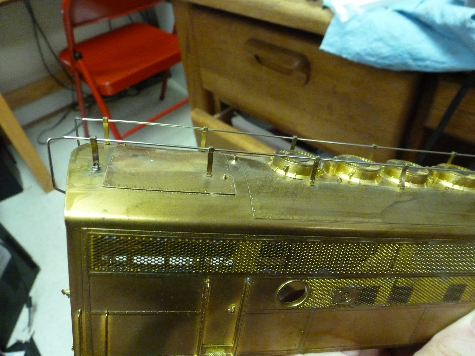
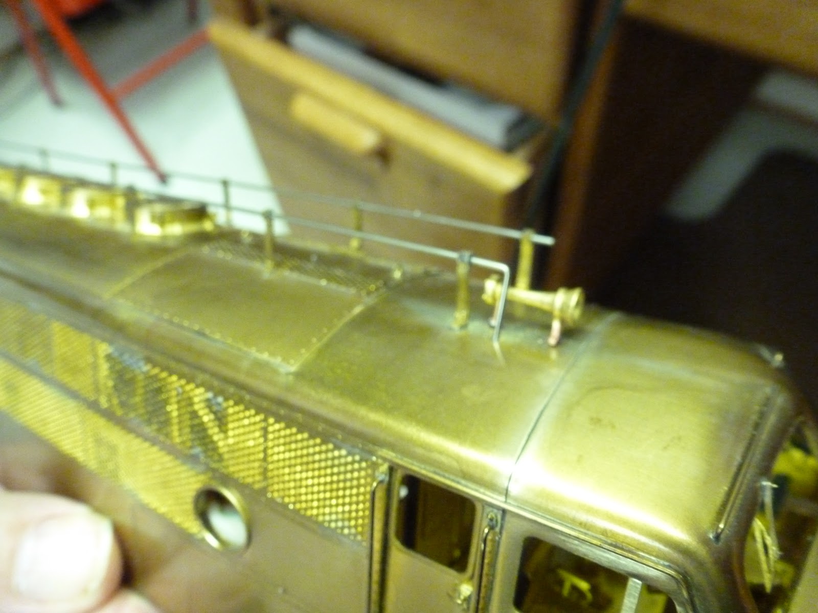
 Overland put steam generator related vents on the roof and the freight units were not so equipped so I had to remove them and fill in the holes ithout damaging the antenna.
 They also had both antennae going down into the roof to terminate. Only one leg did that so we had to cut off the end and then fill the hole in the roof. They provided the correct horn but it had to be mounted.
 As the engines were in service, they added lift lugs to aid in rerailing the units. So, I obtained castings from Bill Davis and P&D to put them on the nose of the A units.
 Another view of the roof patch. I am modeling unit 9501s and 9504 which were in the first sets and assigned to Northumberland in 1950. Some of the details were unique to them.
 Here is one completed engine - the future 9501.
 It looks good to me!
 Here is the set
 Here is 9504 which is one that I bought used in about 1990 - who says O scale takes patience!

They run really quiet and well and are headed out to be painted.