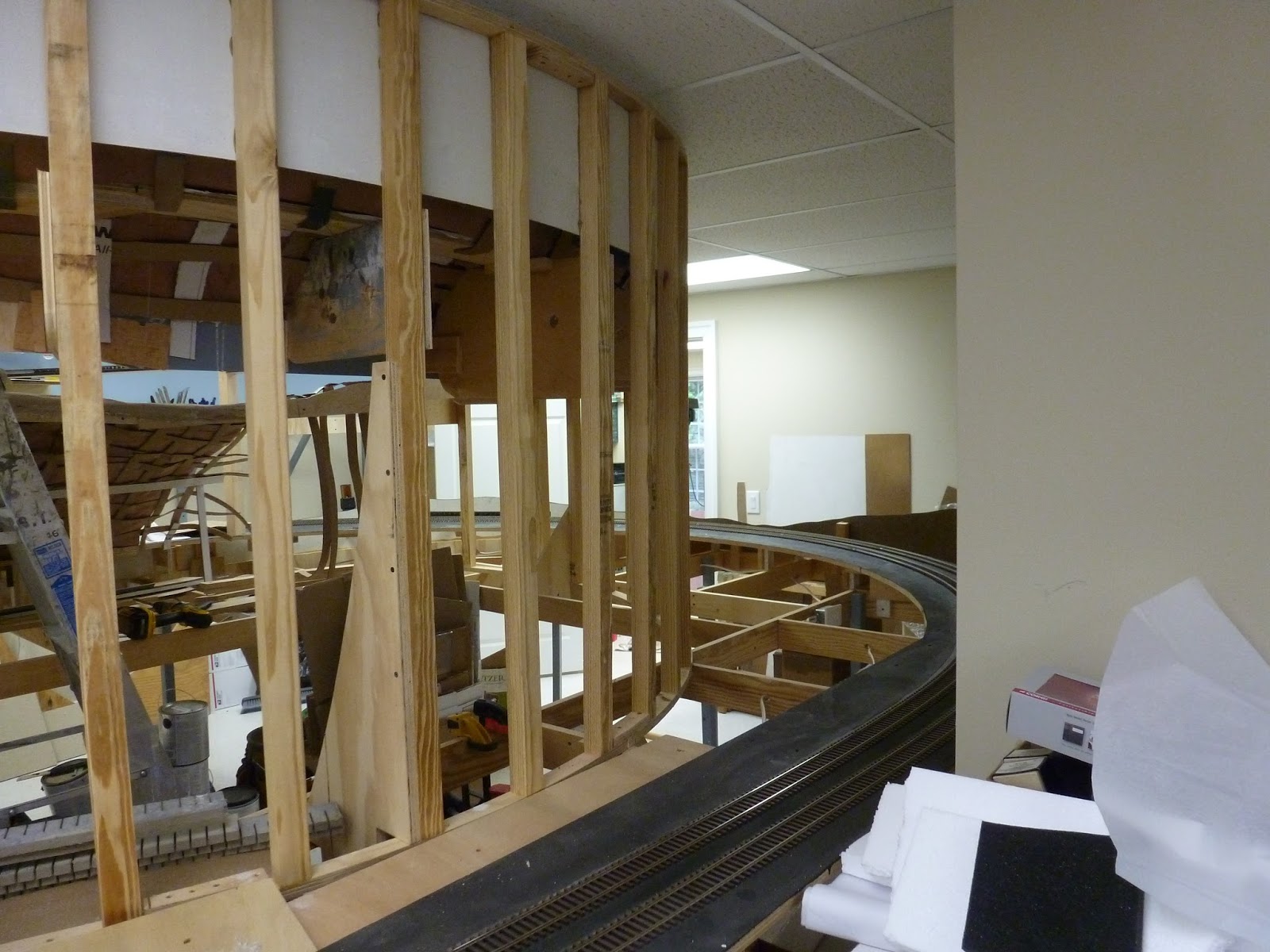
Well, this stud wall that holds up the branch to Mount Carmel has been staring at me for quite a while and I have been trying to think about what to do with it to give me the best backdrop. You can see the branch line substructure on the upper right of the picture.
I have some sheet plastic but that is too inflexible to work with. Masonite is too porous for my purposes. I have been thinking that I would go with a Masonite sub structure and then a plastic top sheath.
You can see that the wall is curved so the backdrop material will have to have some flexibility. It goes around a big curve on one end and a short curve on the other. The radius is about 60 inches.
The area in the foreground will become Milton with some switching and a small town to be built. I have to fabricate the substructure after I get the backdrop up. In the picture below you can see that I will have to remove some angular reinforcers that I put up when I built the wall. They will interfere with the installation of the backdrop.
Well, the angular legs are gone and I added brackets inside the structure of the wall. It is now very rigid.
Here is the end of the wall where it meets the branch coming across a bridge over the aisle. After a lot of internet searching, I came up with using 1/4 inch sheet rock, including a flexible variant of it. I was able to buy it about 30 miles away and purchased two sheets of each.
Well, the work gang came over after I had prepared the structure and we began to hang the sheet rock. We used the normal sheets for the straight section, about 16 feet long by 4 feet high. Then we got to the curved portion. We learned that water was required to be sprayed on the back of the flexible sheets. You had to let it soak a bit and then carefully bend it around the structure. Here we see Paul and Alan up on the bench work, finishing the last straight piece. Jack is providing logistical support.
Jack is now going up to add screws to previously installed pieces. You can look over his head to see the sheets already up.We left the last inversely curved piece to the end.
Now, the pontificator has entered the picture as we debate the best way to secure the end of the first curved piece. It is decided to put a piece of plywood to hold it down to the framing and relieve the stress of beginning the curve.
Paul is not convinced but agrees to go along with the plan as he can say "I cannot see it from my house" to quote my good friend Stan Kos.
So, now I have put up the plywood scab to secure the joint and am now slowly screwing in the sheet as Alan bends it from behind. According to the literature, once the sheet rock dries, it will take a set to match the curve and stresses will be gone. Paul is still not entirely convinced.
Here is a view from the other side as Alan holds the sheet rock, while still spraying more water on the back side of it. I am screwing the sheet every 8 inches to a vertical stud.
After the dust settled, literally, we added to last sheet on the inverse curve and we are now up to having to mud this wall. You can see the water bottle used to spray the back side.
Here we are looking down the main line by Milton and the start of the big curve.
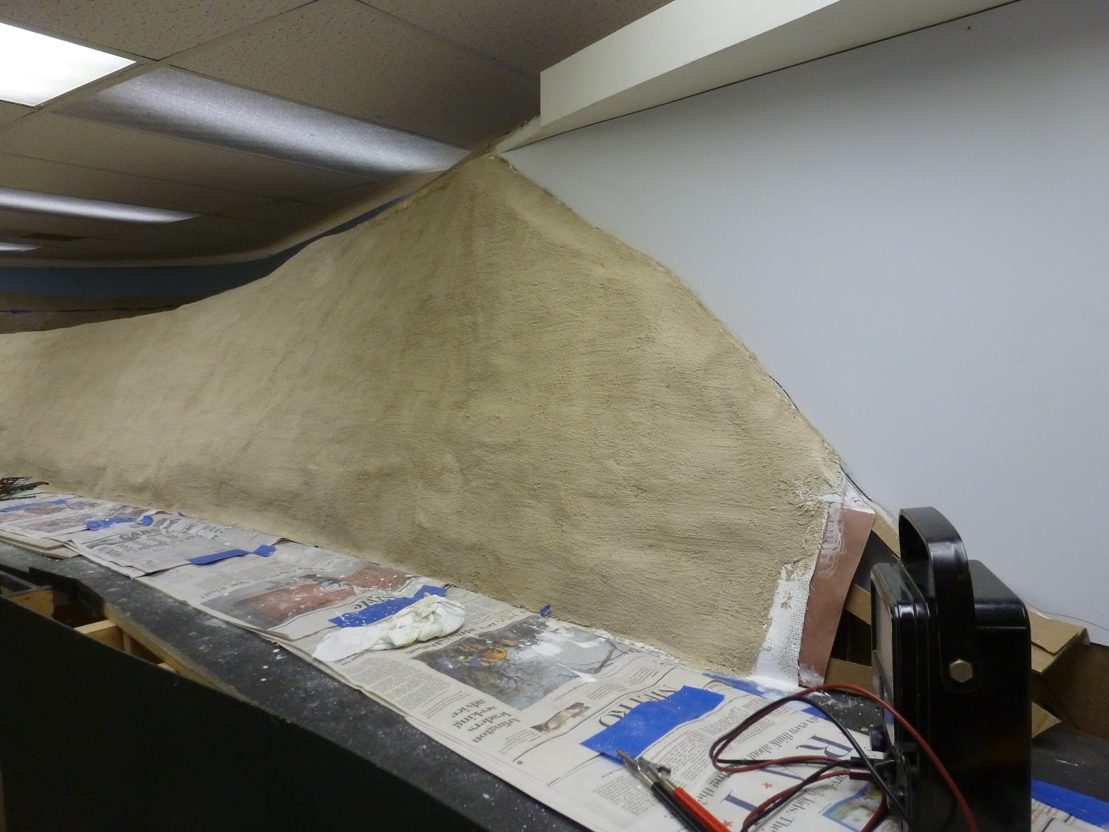
Here is the curve. It has a 4 foot high section that is 4 feet long. Then it shrinks to a 2 foot section that is 8 feet long. There will be a hillside here that goes around to the base of the bridge and meets the hill we have already built.
This is the other end that is 2 feet high. It will have a hillside coming up to meet the sheet rock. You might be able to make out the end of the line up to Mt. Carmel in the far right of the picture. i have to cut off the tag end of the sheet rock to the right of the line of screws.
In summary, I am pleased with the results of the installation. I think it is easier than a combination of Masonite and plastic sheet. So, now I have to evaluate how to accomplish this on the balance of the scenic divider that has to be built - about 90 feet or so. More trips to Hampton for supplies.