Sunday, November 28, 2021

Bringing Back an Old Favorite

We had a fellow in our old train group, up in Washington, DC, who was a good PRR modeler. He bought a Sunset I1 when they came out and super detailed it. He installed DCC and ran it around 50 inch radius curves on his layout for years. It was my favorite when I would go to his house for train night, once a quarter. Well, I obtained the engine on his passing and it sat in a box for a number of years. You can tell it had a lot of use if you look at the pilot truck wheels. 
Well, I took it out during Covid and got it back in service. I cleaned and polished the wheels (here is the pilot truck now), I removed the DCC, installed new lighting and contacts. It had its gear system cleaned and re-lubed, missing screws replaced and generally tuned up. 
Here it is now on my layout, with memories of Doug Jones every time it goes by.  It was one of the first engines in the group to have Grabowski details like the main rods, pilot mounted air tanks and tender details. 
It looks good going by and still runs smoothly. 
It runs up the branch with no problem due to its ability to take a sharp radius. 
It looks good on the main line also
It even negotiates temporary bridges with no problems!
Doug's handiwork rolls on into 2021.
 

A Hopper Project That took 25 Years

Well, back in around 1995, I bought a series of hoppers from Bob Parri who was a gifted scratch builder of hopper and other open cars. This is one of several USRA hoppers that I purchased. I used the Covid time to undertake a big painting project of his cars. 
Here a six N&W twins of his. I had them for so long, I had to sandblast the oxide off, make some repairs from being in boxes, and then add trucks and couplers
I also had a number of triples, both his and also from Precision. They represented various classes of N&W cars. There were about 12 in all. 
You can see my references in the back of the car. I actually used mostly Komar rub-ons as I like them very much. 
Here is the completed fleet on the layout.
I pulled together this Lackawanna lettering for the USRA car as they had some in my time frame. It is a nice looking car. 
Here is a Komar triple
And a Komar War Emergency car.
Then we have the standard twins
More twins

 And still more twins. Glad to have this done finally. The cars would not typically have been found on my layout so probably have to sell them. Would like to have done that before all the work!

New Tenders - Both Scratchbuilt or Modified

The PRR had a special tender that it developed in the hope of extending the range of the K4 by giving it more water capacity. It held 25,000 gallons of water. It was a take off of the tender on the M1a's that held 21,000 gallons of water. They did this by shortening the coal pocket.You can see the impoact by comparing this picture with that of the tender below. It was not really a success so they removed them from the K4 and used them on a variety of engines. They used 10 on the 2-10-0 I1's. They have never been made in O scale. I obtained the drawings for the tender, a set of M1a tender trucks and the usual Grabowski parts (hatch, and drains). I asked Frank Miller to fabricate the tender from this material. It was his last project. Here I have painted it as it appeared in 1956 as it was assigned to an I1. It had had its antenna system removed but the associated equipment box was still on the side of the tender. Frank did a great job and even captured the slant in the side that was on the original. This is going to look good behind the I1 that is in the paint line.
This is the later version of the M1a tender. It is a welded side 210f85a tender with 8 wheel trucks instead of the riveted tender with 6 wheel trucks.  The model is an upgraded Sunset tender that has had an early antenna system installed. This type of arrangement appeared behind some M1's that were given welded tenders during their service lives. The antenna pipe went through the water tank rather than over the deck and down the rear of the tender. They later put the pipe over the deck as an improvement as the pipe was in anther pipe in the water tank - a leakage problem. You can see the antenna appears to be a U-shaped pipe. The model also has Grabowski hatches, antenna details, dog house and drains. It is going to go behind an upgraded, modernized Westside M1, also in the paint shop. It is based on an engine in Don Ball's book on M1's. 

I painted these tenders to get me moving to the complete the painting of the associated engines. I also painted a modified Precision 110 tender (antenna removed) to trail a Precision K4 that had to be remotored and is now in the paint shop also. 
 

Completed the Erie Built Upgrade that started in July of 2020

If you look back at the posing in July of 2020, you will see that I upgraded the drive line of the A-B-A set of these large engines. They were factory painted but had problems with their paint job. So, I had to do some work to get them to look better. Here we can see that I added he missing engine numbers in the number boards. I also put in reflectors in the headlights and removed the silvered backing of the MV lenses. I added constant directional lighting as well. I stayed with the MV Lenses as they were bulbous as the headlight glass was on the prototype. 
Here you can see that I added additional decals used by the PRR to show the front of the engine, as well as the lettering along the bottom batten strip for fuel, electrical connections and water. The large engine number was the one I replaced for the wrong number the painter had put on the unit. I sanded off the decal, sprayed some gloss on the area and renumbered. 
Now the side has more detail. I could not bring myself to sand off all the lettering and redo the side stripe however. Actually, as the engines were repainted after servicing, the side stripe got wider. As I model 1956, this was well after they were introduced and many of them had wider stripes, as well as modified pilots. So, I went with that. 

 I added the front air hose to the pilot opening and that filled it some. I also used a new Kadee coupler, which has a beefy look. I had to completely disassemble all 18 gear boxes, however, as they had a lot of noise. Turns out they had not been lubricated at the factory very well. It took three days to get everything lubed and reassembled. The engines now run great and sound terrific with that larger motor. They have a heavy rumble as they go by. I love it!

Repowering Car and Loco Shops RS11's and RS 12's

Well, one of my projects that took about 3 months with parts delivery and exchange of gear boxes was to take out the C&LS drive which has a 36volt motor and put in a 12 volt motor with a new gear transfer system. This provides much, much better low speed performance and torque, allowing the engines to start a train and avoiding jack rabbit starts. You have to bring your model's frame down to the bare essentials. You can leave the trucks in place.
Here we have the factory installation. It has a flywheel and an unmarked Pittman motor. I worked with Jerry Criswell of Right Of Way who has developed this following system for repowering the models. 

This view shows the C&LS gearbox removed as it will be modified with ball bearings. The motor will be disassembled for parts to reduce he operating voltage in a future use on another project. 
Here we are awaiting the new parts. The replacement process is the same for both the RS11 and RS 12 models. My project had me nervous because I have four painted models. You can see the hood lying on its side. It has constant lighting, etc, already installed.


Here is the new drive installed. We have a modified gearbox, a gear head motor by Fulhaber and a strong, heavy base for the system. 
The modified gearbox goes back onto the original mounting holes and four new mounting holes are drilled for the motor and gearhead. The wiring goes back in place. The brass plate on the gearbox contains the ball bearing.
The engine ran beautifully on the layout
It just started at a creep and went around smoothly.
One down and three to go.

 Now the engine pulls as good as it looks. I was very pleased. Each engine took a full day to complete.

Developing the Diesel Engine Terminal


Well, we will start with improving the diesel engine facilities. In an earlier post, I showed how I built and wired the whole area. Now I have to begin putting the scenic touches in. 

I had spaced the track to accept an IHC Enginehouse Kit as my diesel house. Unfortunately, I had mis-measured the spacing for the end walls. 
So, now I have to move the last two tracks further apart. 
This is the problem. The kit added wall spacers on the sides of the end which I did not notice. So, the tracks have to move right. Fortunately, we have the space to do it. 
There is sufficient space from the end of the garden tracks of the steam area to allow me to shift right. 
So, I unsoldered the power feeds to the sides of the rails. I had one track as a common so that eased the burden somewhat. I also pulled the spikes on the flex track. 
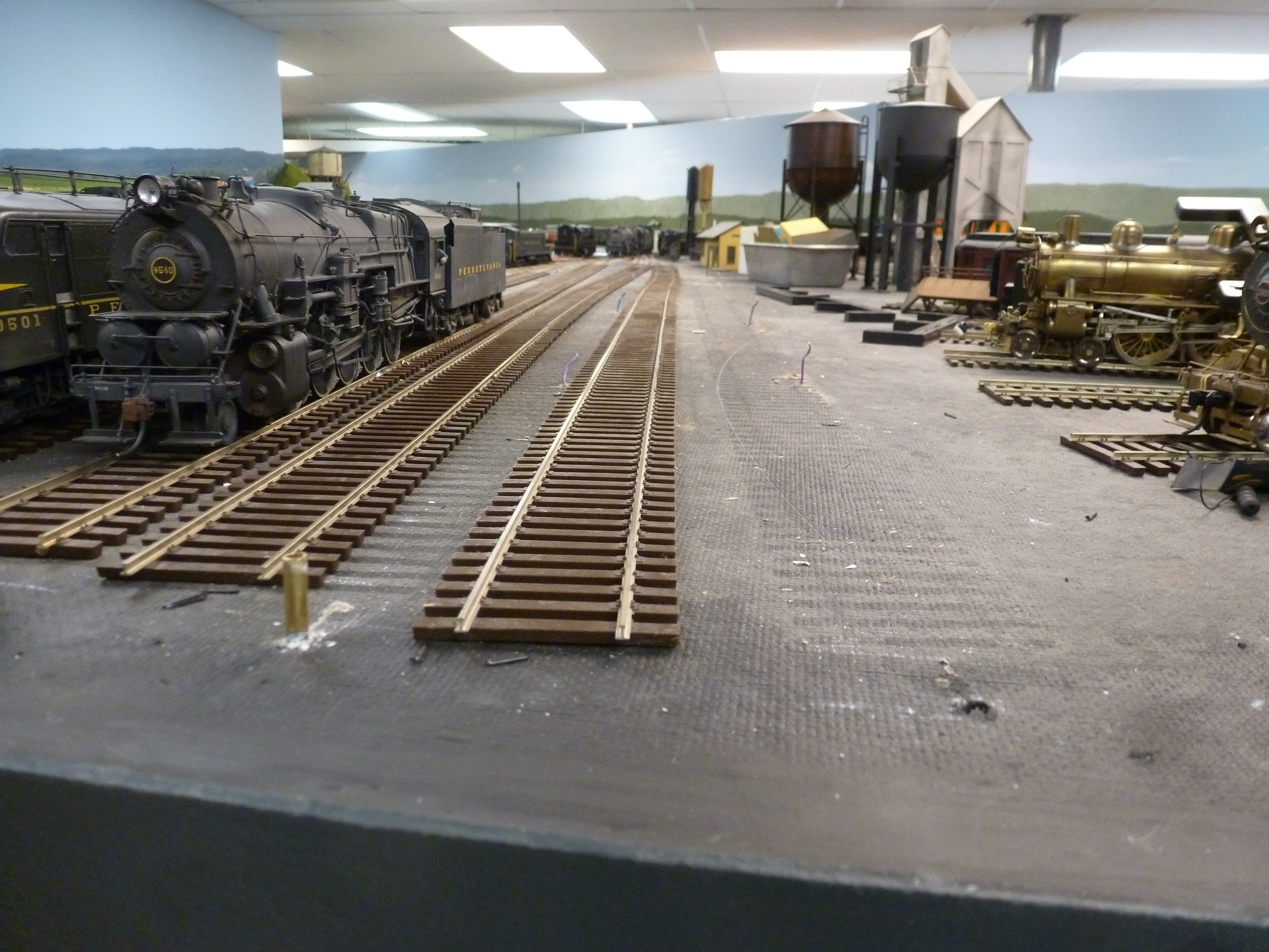
Now you can see how much flex I had to move the track. I cleaned the area up as I began. The steam engines are sitting there as the steam terminal has not been wired yet. 
I pulled the feed wires up so I could easily see them for future connections. 
Now I am mocking up the locations of the tracks, using the wall spacing that comes with the kit. I have already mortared the joints in the brick walls. It really enhanced the appearance of the kit. 
I am estimating the space between the last engine and the wall, shooting for about 5 feet as a walkway. 
Here is an overview of where I am coming out. 
Looking down the other way. I had to replace one rail in a switch as the gap was made too large by moving the track lead. 
.
The new look prior to painting. I had soldered new feed to the track and made connections to the original feeds under the table so no real disturbance to the wiring. 
The track is now painted and cleaned up. I tested all the spots for connectivity and made any minor adjustments. required. 
Now I have redrilled the base for the brass tubes that hold the bumpers in place and reinstalled them all. 
This is how the interface with the building and the garden tracks will look. Minimum is about 5 feet. I need to come up with a bumper system for this area.

Next, I have to develop the fueling installation and the integration of the sanding towers. I also have to make a floor for the building and then ballast around it all. You can see a potential arrangement of the sanding towers beyond the building.