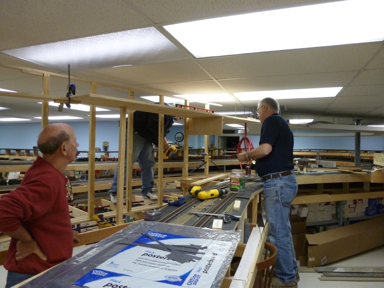
Okay, this is where we were when we last took shots. The wall is in but needs some minor modifications to allow the light lens to be opened should I ever have to replace a bulb. I will cut down the end to allow a swing.
The curved wall is essentially placed but I have to build out from the opposite wall to reach it. I have temporarily put a brace to hold the end of the line.
This view shows how we have to climb up the wall to reach that red wire way in the back where we will make the joint with the existing (for 3 years) hanging loop,
Jack Brown (in blue shirt) and Walt Johnson are readying the joint - we have to biscuit the roadbed we are bringing up to make the joint strong. We cannot place a spice piece as there is no room. Rich Feller is in the rear marking the locations of the biscuit holes that I will have to match when I cut the roadbed. He is standing on the existing bench work that is holding the wall up.
Okay, the work is now all done and this is what we have - here is the temporary roadbed spanning the aisle with a 2X4 in the location where I will have to build a tall pier to hold up a joint between a through truss and a deck truss to cross the aisle and the lower main line. The blue clamp to the right holds a piece that shows me how far out I will have to build a piece of curved benchwork to support the pier on the right side of the through truss. The paper hanging down is my list of things to do to complete everything.
Standing at the other end of the grade, you can see the design of the braces that support the roadbed. Walt drilled holes for the wires to be pulled through that will power everything.
As we go down the grade you can see the ends of the braces have been rounded as Walt was cutting his head open each time he hit the square corners. So, for self preservation, he rounded the ends of the braces and now his scalp is healing. These braces will have plaster covering them as I will have an apron on the roadbed so when you look over the hill from where I am taking this picture, you will not see them.
Now, we are down the grade to where the bridges will be. I have to build an end to a hill to disguise the end of the wall. It will have the bridges coming onto the hill side which will rise to the left to cover that wall. The hill will then drop down to the main line below as it sweeps around in a curve.
This shows how the benchwork will have to bump out to pick up the pier of the bridge. My friend, Pat Mitchell,who built scenery for a living, showed me how to make the curved structure that I will use in this area. I will have to tie it into the existing benchwork so it is rigid and will be able to withstand the inevitable head knock on the bridge.
Standing on the other side of the wall, we will have the main line sweep by us at the base of the hill as it comes into Milton. You will not see the track on the other side of the wall.
This is the other end of the future Milton, where the track disappears into the lower holding area. I have begin to lay the plywood for the town in the foreground. That pretty track structure up on the wall will soon disappear as I lay masonite up on the wall.
Thursday, March 7, 2013
Sunday, February 17, 2013
Building the Way to Mt. Carmel
Well, the civil work continues as we have to build a wall to divide the room and also hold the roadbed for the tracks up the mountain to Mt. Carmel, the hidden loop. It has been sitting there for about 3 years as I build everything else. This shot shows the curved plate and shoe of the wall, which will rest on the bench work. The roadbed is cut also and sits inside of the narrow shoe. I will use ripped 2x4's. cut to 48 inch lengths, to make the wall. One of them rests on the roadbed in the foreground. Just for the record, the wall is a 60/61.5 inch diameter circle and the roadbed is a 53 inch radius curve.

Walt is looking at the bottom of the curved section as we decide where we are going to cut it to begin the straight section to run down the length of the main to the hidden section.Over his shoulder you can see the bridging piece of benchwork that is going to be picked up by the wall we are building. I am having a little problem as the wall is not plumb yet so we have to add braces to make it plumb.
In our last shot we are looking from along the side where the grade will go into the overhead loop.
I have to make the wall start in a way that allows me to use two bridges to cross the aisle and tracks of the main line. A bump out, shown by the piece held by the clamp on the right side of the roadbed where it comes off the wall and crosses the aisle, will be constructed to pick up the pier holding the right side of the bridge. The through truss bridge will go 40 inches to a pier on the left side of the main line. We will then have a 20 inch deck girder to make the transition to the hillside. A curved backdrop/wall will then carry the line up to the ceiling.
| A friend of mine, Walt Johnson, is putting in a stud. |
We started the wall by building the curved sections on the floor and then raising them up to the bench work. We have about 2 inches of clearance to the ceiling. The second purpose of the wall is to avoid having anyone seeing the other side of the room. At this height we can be sure we will not have that happening. A train climbing up the wall will be low enough that it will not be seen by people on the other side of the wall
Walt is looking at the bottom of the curved section as we decide where we are going to cut it to begin the straight section to run down the length of the main to the hidden section.Over his shoulder you can see the bridging piece of benchwork that is going to be picked up by the wall we are building. I am having a little problem as the wall is not plumb yet so we have to add braces to make it plumb.
We now have the straight sections up and are looking down to the overhead track. You can see the end of the curved wall. . In the distance, the wall will turn radically left to cover the opening for the lower hidden tracks. I can now put in the bracing on the wall to hold it plumb as I build the roadbed on the other side.
Saturday, January 5, 2013
Setting the grade to Shamokin
This is an overview of the latest progress. I have gotten the plywood sheets for the roadbed of the branch, the sidings at Glenbourne Colliery, and the bridge over the aisle in place and temporarily placed them on risers to gauge the impact of the 3% grade to the bridge. Looking across the two aisles, you can really see the severity of that grade. I am a little concerned about the limits that will place on the equipment but I have to keep the bridge high enough to provide 6 feet of clearance over the aisle. I am trying to picture what a 25 car trains with four engines will look like on this hill.
The town of Shamokin will be where that bookcase is standing now. The benchwork will continue to the wall there.
The grade does not look so bad when sighting down the right of way from the end of the curve of the Narrows. Sort of makes me feel better.
The grade again looks steep when looking from the east end of the line. The plywood subroadbed over the aisle is placed to give me a reference point for continuing the roadbed on the other side of the aisle. It will be cut out when I place the bridge permanently. I have to build a whole new wall structure to provide both a scenic divide and a support for the roadbed climbing up to Mount Carmel which is hanging from the ceiling. Shamokin is going to be what rises to the right side along the wall where the plywood ends currently.
Standing on a stool, you get a view looking back down the grade and can see where the base is for the colliery sidings.
This us a view showing where the backdrop will rise up to pick up the roadbed. The line will cross over the summit of the back drop and go from the side where I am standing over to the side which is visible from the aisle to our right. It will then continue to rise up to the ceiling down in the back where the red wire is hanging down. I cannot imagine if I have another derailment like the one I just had with an I1 plunging to the floor from this height!
Thursday, December 20, 2012
Disaster Strikes
Well, the engineer on a double headed coal extra was not observing Rule G when he took the controls and brought the train out of Northumberland and headed up the branch to Weigh Scales. In Reed, he hit an obstruction on the track and derailed. The rear engine continued pushing and pushed him right off the roadbed into a ditch that was about 58 inches to the concrete floor. These pictures illustrate the damage that took place. The engine fell onto the pilot and crushed it. The engineer was gratified that his rebuild work on the pilot tank assembly was not affected.
The engine then rolled over at some speed and crushed the headlight into the boiler. The smoke box front exploded off the engine with that blow. It took some time to find it as it was at some distance from the wreck.
This is what happened to the pilot truck. It must have whipped around and then been bent by the cylinders.
The tender remained coupled to the engine until it hit the floor. It bent the drawbar into a U shape and tore off the cab apron before it separated.
The rear of the tender then whipped down and hit the floor, crushing the tail beam on one side and ripping off the base of the antenna.
We are hoping that the shop forces can repair this engine and upgrade it with the new fixtures that we were planning on putting on the fleet. It has now been moved to the head of the line for attention. Thank good ness it was not one of the engines already rebuilt by Frank Miller. There would not a report in that case, just crying.
The engine then rolled over at some speed and crushed the headlight into the boiler. The smoke box front exploded off the engine with that blow. It took some time to find it as it was at some distance from the wreck.
This is what happened to the pilot truck. It must have whipped around and then been bent by the cylinders.
The tender remained coupled to the engine until it hit the floor. It bent the drawbar into a U shape and tore off the cab apron before it separated.
The rear of the tender then whipped down and hit the floor, crushing the tail beam on one side and ripping off the base of the antenna.
We are hoping that the shop forces can repair this engine and upgrade it with the new fixtures that we were planning on putting on the fleet. It has now been moved to the head of the line for attention. Thank good ness it was not one of the engines already rebuilt by Frank Miller. There would not a report in that case, just crying.
Needless to say, the engineer will be disciplined with some time off and subsequent assignment to the shop forces to hone his skills on repair work! We will have to supply after pictures to show what came out.
Coninuing the branch line construction
Well, as we look down the wall, we have added the framing for the first section which is rectangular and will hold the Glen Burn Colliery. It is conventional box construction, using the brackets already mounted to the wall and knee braces.
Looking back, you can see where the box ends. We are trying to gauge the length of the cross members, using our flexible plywood held in place by the yellow clamp. The frame will shrink to match the curve of the side of the benchwork on the left which holds the mainline.
Another shot of this effort. We have now cut the cross memebrs and will install them.
Cross members are in and we modified the depth of the knee braces as we are down to a length of one foot for the cross member. We have to get this short to allow that three foot aisle minimum to be maintained.
Now we have placed the two layers of flexible plywood and glued them together in a somewhat smooth curve. The clamps are holding them to dry. At this point the benchwork is approximately 68 inches high. The track will be about 72 inches high when it crosses this aisle.
Looking down the wall.
I am up on a stool to get a downward view so you see the curve. We are about 16 feet to the end of this run.
This shot shows that we have placed the plywood onto the benchwork. We are now trying to get the curve in place that will allow the line to cross that bridge at about an angle of 120 degrees to the aisle.
This is proving to be difficult due to the narrow size of the bench top. I am looking into moving the crossing further back to give me more room to make the curve. I am trying to get the bridge to cross where the main line is closest to the right edge - near wherre the yellow/white cap rests on the track
Looking back, you can see where the box ends. We are trying to gauge the length of the cross members, using our flexible plywood held in place by the yellow clamp. The frame will shrink to match the curve of the side of the benchwork on the left which holds the mainline.
Another shot of this effort. We have now cut the cross memebrs and will install them.
Cross members are in and we modified the depth of the knee braces as we are down to a length of one foot for the cross member. We have to get this short to allow that three foot aisle minimum to be maintained.
Now we have placed the two layers of flexible plywood and glued them together in a somewhat smooth curve. The clamps are holding them to dry. At this point the benchwork is approximately 68 inches high. The track will be about 72 inches high when it crosses this aisle.
Looking down the wall.
I am up on a stool to get a downward view so you see the curve. We are about 16 feet to the end of this run.
This shot shows that we have placed the plywood onto the benchwork. We are now trying to get the curve in place that will allow the line to cross that bridge at about an angle of 120 degrees to the aisle.
This is proving to be difficult due to the narrow size of the bench top. I am looking into moving the crossing further back to give me more room to make the curve. I am trying to get the bridge to cross where the main line is closest to the right edge - near wherre the yellow/white cap rests on the track
Thursday, December 6, 2012
The actual layout design
Well, I have been asked multiple times about the actual design of the layout. So,here are the working drawings from 3rdPlanit that I have been using as I build. This first drawing shows the main line in the center of the room in black. The overall distance on the diagonal is about 70 feet. You can see that I have had to deal with a very odd shape to the room. The two lobes on the right side were wide enough so that I could get return loops in while maintaining a 62 inch minimum radius on the main. The main line ends on this drawing - where it goes into the hidden yard which is below the main yard.
You can also see the outline of the branch line benchwork on the wall going around 3/4's of the room starting at the bottom and going up to the top wall. My problem was getting the branch around the lower left turn where the wall rises from the bottom and turns left. I had to squeeze in the branch, a 3 foot aisle and then 9 tracks in the yard/main of Northumberland. To do it I was forced to reduce the aisle to 28 inches for about 2 feet right at that corner.
This drawing shows the main line and the hidden yard. It starts where the main leaves the upper yard (Northumberland), which is visible. You can now see the branch line in red. I used this drawing to figure my grades as I went from the base elevation in the hidden yard to the upper yard. I placed that 9 inches above the hidden yard and ended with a 1.75% grade. This allows me reasonable train lengths with the engine lash ups I plan to use. I used the branch line drawing to see what grade I needed to be able to cross the aisle at the top of the drawing with a through truss and have people be able to walk under it.
This is last drawing that I used to compute my track lengths for materials. It shows the overhead loop in light green added to the end of the branch line. You can see the branch track crossing the aisle at the top of the drawing. You come in that top door on the right and walk along the wall until you turn right at about the mid point of the room. I am making a field change by moving the aisle crossing to the left as I realized I cannot get a 40 inch straight section ( the bridge) in place and still make the curve I need to turn back to the overhead loop. So, the new location of the crossing is about 1/3 the way down the aisle from the door. This has forced me to increase the grade to 3% from the 2% it is up to Weigh Scales. This is actually prototypical as the grade stiffened beyond Weigh Scales in real life.
So that is the design. It took me about a year to get everything figured in due to the shape of the room. I originally want to have the yard on an outside wall and the branch climbing through the center but could not get that to work. This design allows the branch line engineer to walk with his train and accomplish the switching I enjoy, while having main line trains run through the layout until we need to change engines or blocks of cars. I have done research on he scheduled freights that ran through Northumberland and will try to incorporate them as well as the passenger trains. I plan to use the branch as the line to Wilkes Barre also to add diversity the trains heading up and down the line. I can run some way freight on the main, but it is not as convenient for the operator. The control system will be conventional DC with Tower Operators like on the PRR.
More later.
You can also see the outline of the branch line benchwork on the wall going around 3/4's of the room starting at the bottom and going up to the top wall. My problem was getting the branch around the lower left turn where the wall rises from the bottom and turns left. I had to squeeze in the branch, a 3 foot aisle and then 9 tracks in the yard/main of Northumberland. To do it I was forced to reduce the aisle to 28 inches for about 2 feet right at that corner.
This drawing shows the main line and the hidden yard. It starts where the main leaves the upper yard (Northumberland), which is visible. You can now see the branch line in red. I used this drawing to figure my grades as I went from the base elevation in the hidden yard to the upper yard. I placed that 9 inches above the hidden yard and ended with a 1.75% grade. This allows me reasonable train lengths with the engine lash ups I plan to use. I used the branch line drawing to see what grade I needed to be able to cross the aisle at the top of the drawing with a through truss and have people be able to walk under it.
This is last drawing that I used to compute my track lengths for materials. It shows the overhead loop in light green added to the end of the branch line. You can see the branch track crossing the aisle at the top of the drawing. You come in that top door on the right and walk along the wall until you turn right at about the mid point of the room. I am making a field change by moving the aisle crossing to the left as I realized I cannot get a 40 inch straight section ( the bridge) in place and still make the curve I need to turn back to the overhead loop. So, the new location of the crossing is about 1/3 the way down the aisle from the door. This has forced me to increase the grade to 3% from the 2% it is up to Weigh Scales. This is actually prototypical as the grade stiffened beyond Weigh Scales in real life.
So that is the design. It took me about a year to get everything figured in due to the shape of the room. I originally want to have the yard on an outside wall and the branch climbing through the center but could not get that to work. This design allows the branch line engineer to walk with his train and accomplish the switching I enjoy, while having main line trains run through the layout until we need to change engines or blocks of cars. I have done research on he scheduled freights that ran through Northumberland and will try to incorporate them as well as the passenger trains. I plan to use the branch as the line to Wilkes Barre also to add diversity the trains heading up and down the line. I can run some way freight on the main, but it is not as convenient for the operator. The control system will be conventional DC with Tower Operators like on the PRR.
More later.
Saturday, December 1, 2012
Beginning work to complete branch line
| Looking westward |
I am standing where a representation of Shamokin will be on the wall to my right at about my head height. The Glen Bourne colliery will be above that cardboard (gathered for scenery forms) leaning against the wall.
Walking down to the corner, we come the the curve leading to Weigh Scales which is our gathering yard. We have the river on the outboard side, PA Highway 61 is to the right of the track and high on the hill is an S Scale track to represent the Reading line through the Narrows.
This is a more complete view of the Narrows. Weigh Scales is just around to the left where my electrical supplies sit. The track is rising on a 3% grade to make the climb to get the bridge over the aisle to about a 72 inch clearance from the floor.
These last two views are looking back at where we have come from. A good view of the Narrows with Shamokin Creek in the foreground in the first shot. The second shot gives you a view back to where the bridge will be. The line will then curve around to the right over the existing main and continue to rise about another 8 inches to meet the holding tracks over my right shoulder. We are having active discussions about how to scenic this whole thing but more on that later.
| Continuing to the west towards Weigh Scales |
| The Narrows with the Reading high above |
| Looking at the Narrows but back eastward |
| Looking back eastward to where we started |
Subscribe to:
Posts (Atom)