Wednesday, September 14, 2022

Finishing the Shamokin Turnout Track Complex

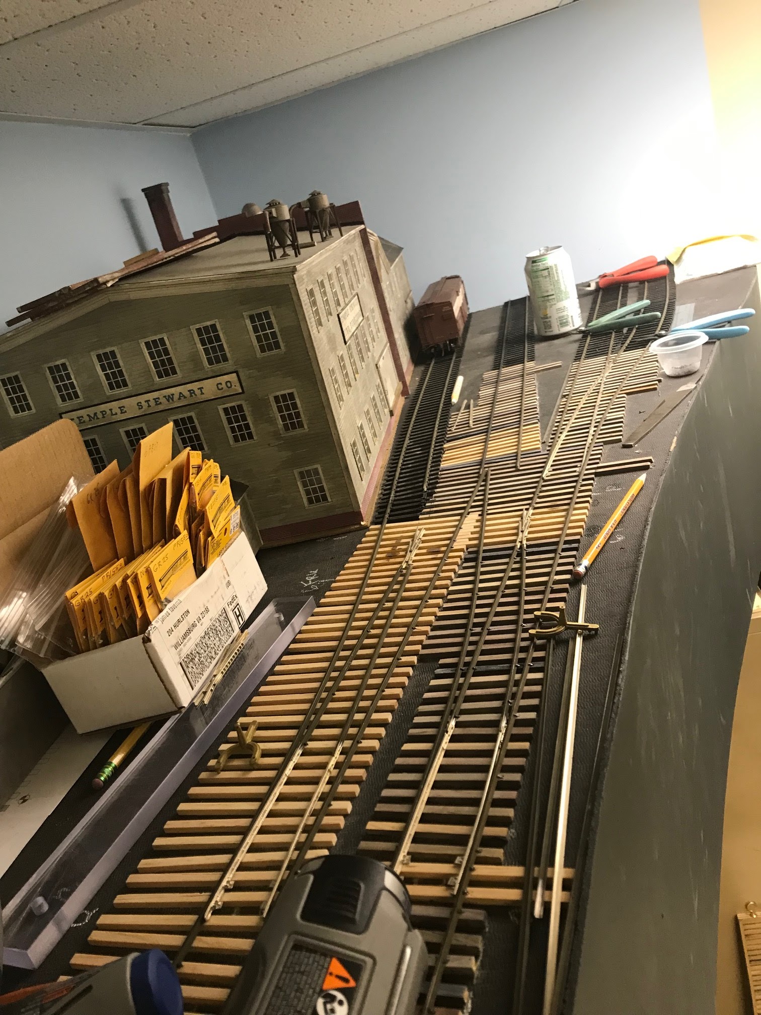
Okay, the ties are sanded, and I have assembled my supply of points and frogs next to the factory. That factory is a bit of a problem as it has a fire wall in the middle of the long wall that juts out and that is putting a little pressure on my first turnout placement. I have to have the track a little further from the wall than I figured initially. I am beginning to place my components and test for fits. 
The turnouts have to fit pretty close to plan as they flow from one directly into another and they are all co-dependent. You can also see my white pencil as I have been checking my frog locations. I found I had to shift to a No 7 frog on the last one to make it all come together. The team track, which are the last two tracks to the right of the soda can, has the No 5 turnout as it is in a short space. 
I am beginning to lay the turnouts. I use those Kemtron tack gauges as they allow you to spike around them., 
We are getting closer as the two leading turnouts are in. The points are not connected but they are tested with the truck that is in the foreground. It runs smoothly through them. I have gotten the track in next to the building with enough clearance for an engine. 
Okay, now all the turnouts are laid, and I have placed some pewter based guard rails at each frog. Everything runs smoothly and I now have to install the motors. 

Motor linkages are sticking out of the point bars, and I now have to cut the spring wire to length

Here is a high level view of the installation. I am beginning to cut the ties to length. 
This is a close up of the point bar with the spring wire before trimming. I also cut the brass studs that the points are bolted to. 
This is a completed turnout. Brass studs cut down, spring wire cut and a closer view of the pewter guard rails. These were made by Harry Roberts some years ago. I used up the last of what I had on this installation. 
 Next, we have to install the wiring to the track and the frog and then paint the track. Another week to go. 

Building into Shamokin

Looking up towards the end of the benchwork, I need to develop a way to bring in a local freight and allow the engine to run around its train. The engine will then switch in Shamokin and also can switch the coal mine at the other end. This will require a long passing siding that terminates in a turnout complex. 
This is completed track work back towards the mine. The branch is coming up the hill on the left and the mine tracks come off at the curve.  
As we come around the curve leading to the bridge, the Shamokin track branches off to the left and moves towards the rear wall. 
I plan to place this big furniture factory in the rear corner. I am laying out turnout diagrams to see how I can create that run around track, a siding for the factory and a two track team track on the right. I find I need at least 23 inches from the end of the last set of points to the wall to allow an I1 with a short tender to clear them. 
Based on that planning, I laid out the locations of the 4 sets of point bars that I will need for the complex. I used that large drill to drill the holes for the switch motor linkages and begin to lay the ties. 

 I continue to check and recheck the positioning and use three different numbered frogs to make it all work. There are two No 6, one No 5 and one No 7. Those diagrams are very helpful in this and fortunately, available on the internet. I have painted the Homasote black as a sub-base for the ballast. It allows me to use a white pencil to notate where the points, and frogs will be placed. 

I will proceed to lay all the ties and let the glue dry for a couple of days. Then I will sand them all. 

Continuing trackwork in Glenburnie

Well, we finished the turnouts in Glenburnie and now we have to put in the sidings. I take older issue Atlas track and remove the large sized rail. This leaves me with many one foot long sections of the plastic tie strip. I sort through what I have salvaged and select what I want to use for the sidings. 
Gathering up my track tools which include a beefy Dremel with a cutoff disc, I get organized. I am going to use pre-weathered Rail Craft Code 125 Nickel Silver rail in three foot sections. The rail sections are laying on the handles of the red pliers. 
I slide this rail into the clamps on the tie strip which holds in very nicely. This rail is a match for the casting from Trackside Specialties so is perfect to build our turnouts and then use for our running rails. 
Here the pile is shifting towards completed three foot sections of track


Having made about 12 sections of track, I am laying the siding tracks using a gauge to ensure they stay nice and straight. I solder the joiners between the sections after I buff off the rail brown paint on the side of the rails. Then I added car stops at the end of the tracks. 

 Here is a long view with the sidings completed as I begin to scope out the tracks that will come into Shamokin. We can see there is about a two inch elevation increase between Glenburnie and Shamokin.

Wednesday, July 20, 2022

Finishing the cab detail on the GP9 with those cab awnings. Job Done!

Well, this is a project that has languished for about a year as I finished the whole engine but was concerned about how I could model the retractable cab awning on the PRR GP9 cabs. My friend Lee Turner gave me the idea when he sent me a photo of an excellent job he did to model this some year ago. 

 So, here we have the finished cab. One side will have closed windows, which is the fireman's side. The engineer's side will have open widows so you can see him. This is the open window before we build the awning. 

Here is the closed window with the shade furled. I used cigarette paper, per Lee's instructions, and painted it a tan color. 
This gives a better look at it. 
Here I am making the open shade. The cigarette paper is glued to the brass rod, and then painted. The paint stiffens the paper and allows me to glue it with canopy glue to the side of the cab. 
Here is the finished engine with the fireman's side towards us. 
It has all the PRR lettering that they came out with. The antenna addition is a pain to build but it really makes the engine look distinctive. 
Here is the engineer's side with the shade open. 
Here is the relaxed and cool engineer enjoying the fresh air. I will do a little weathering but these engines were new in my time frame. 

My engine does not look as good as Lee's, but I think I captured the effect. The engine is now running with another, later model GP9. These are by Oriental. Next out is an RS1 with a longer shade. 
 

Throwbars

So, I fabricate the throw bars from double sided printed circuit boards that I cut in to 1/4-inch-wide pieces about 2.5 inches long. I drill three #56 holes along the centerline. The outer two holes are spaced 28/32" of an inch apart. Then I put 00-90 screws into the two outer holes to secure the Right-O-Way points. I use 16-foot points for these #5 and #6 turnouts. 

The screws stick up enough for me to get the points mounted on the layout.  They just barely fit into the holes.

Then I solder the screws to the bottom of the two-sided PC board. No worries about these coming out in service. 
Lastly, I cut the cladding on both top and bottom so there is no conductivity between the points which are powered from the stock rails, along with the diverging route rails. This makes them suitable for DCC as well as DC. 

Next you will see them installed. 
 

Continuing the track laying

Given that I am working near the ceiling, I have to find a way to look at the track alignment, so I decided to use a mirror to look down the line. It really helped. 

So, now I have begun to lay the ties, using a straight edge to align them coming off the branch line. After they are glued, I place two heavy weights onto the ties to be sure they are fully into the glue. I also used a piece of Atlas track as a guide to be sure I had consistent spacing of the ties. 
Now, here is the first section glued in place. I have to get the second turnout laid out, so it flows into the second siding track. You can see the center line of that track coming out from under the turnout template beyond the raw ties in the picture. 
I used a shorter straight edge to align these, and also used the Atlas track as an additional guide. The weights are holding down the ties after they are glued. 
Now everything is glued and firmly in place. I have to get my sander and sand to be sure everything is level. The yard here is bowed as it is leveling out from an upward grade.
Okay, we have sanded everything and vacuumed up the dust and we are ready to lay the first turnout. First, I use the template to locate the frog. This gives me a starting point, so I am consistent with the templates.
Frog is in, the two stock rails are down and the points fitted. I am using my mirror to check the flow and it looks good. I also have a truck with my wheelsets sitting here as I use it to make sure everything flows and there are no binds with the flangeways. 
Second turnout has its frog in place, and we are flowing from the first into the second siding. You can see the track is resting in place further down the line. The mirror is always close by.
A closer look at the second turnout. I am also checking the fit of the guard rails. These are Harry Roberts pewter cast guard rails. 
Just for the record, this is how I am working. Standing on the stool on top of the bench that Alan made for me so we can switch this area. If I shift too fast, I can topple over. Almost have twice. Now you know why I am using the mirror! Not too comfortable a position.
Both turnouts are nearing completion so I can cut the ties to match their flow. Phone is there as I got tired of jumping down to answer it!
The guard rails are now going in place. You have to be sure that the flangeways are the correct width. I found that the #6 bolted frogs in code 125 by Right O Way had narrow flangeways, so I had to grind them out. 
We are looking good now. Next, I have to make throw bars.


 Here is an overall view. Throwbars are in the next installment.
Wednesday, July 6, 2022

Finishing the '34 Ford Pick Up

So, you saw this when I was priming the Studebaker in an earlier post. It is an inexpensive 1934 Ford die cast model that I disassembled and painted as I described I was going to do.
This is the reassembled truck next to a similar starting point for the next one. I think these cars cost me $5. 

I painted the fenders black as was common, the body dark green and left the chrome on the headlight housing. I painted over the chrome wheel hubs, bumpers, and taillights. I silvered the doorknobs and painted the interior. I kept the running board looking like rubber and I painted the roof to look different like canvas which was painted. The driver is an inexpensive Chinese made sitting figure. 
Here is the start and the finish. It doesn't look like a rod anymore.
It should look good on the layout. I have to find something for him to be carrying. Plus I need a black license plate holder and a license plate.